By now I have been working on this project on and off (mostly off) for about 8 months, so I reckoned I should maybe write something about the progress so far. :) Also, be sure to stay away from the product page, it contains a lot of undefinitive information and jekyll bodgery (which I definitely spent way too much time on).
Project origin
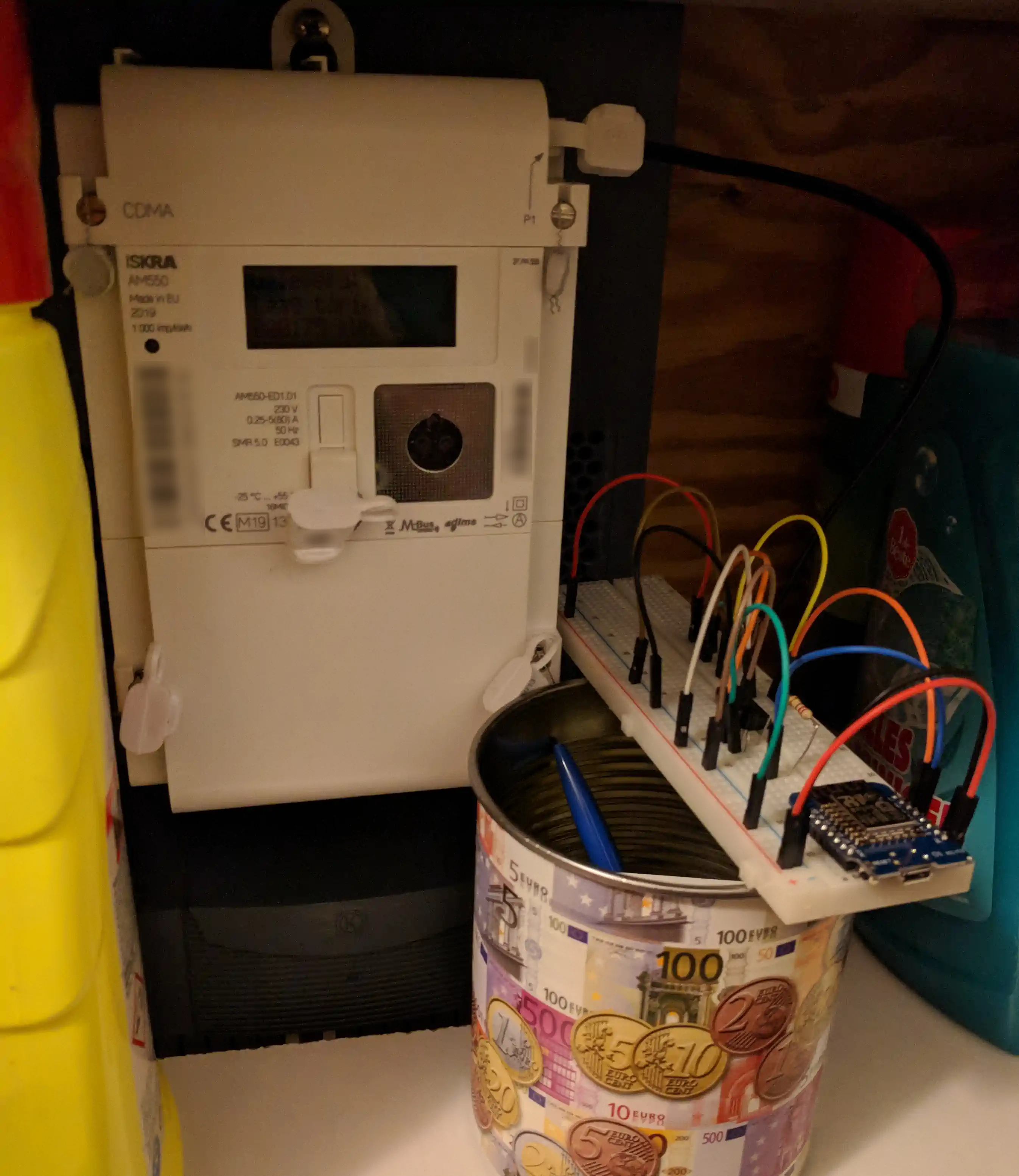
In August 2019, a “smart meter”, ESMR 5.0 compliant, was installed in our home; it replaced the 27-year-old electromechanical induction meter. (D|E)SMR is the Dutch Smart Meter Requirements standard. Among other things, it specifies serial ports for internal and external communication, of which the P1 port is of particular interest. The P1 port (specified in the P1 Companion Standard0) allows the end-user to retrieve data from the meter via a serial interface; the kWh readings, but also current, voltage, that sort of stuff, and periodically also the reading of the gas meter, if one is connected. Also, since v4.0 the port is required to provide 5V power supply. For v4.x this is limited to 125mA, in v5.0 it has been raised to 250mA. That is enough to power a microcontroller!
Of course, I was curious what data could be retrieved out of the P1 port on the meter; I had seen quite some hype over these meters when they were beginning to be rolled out. The same day I built an RTL inverter (video) on a breadboard, the next day I used it to hook up my laptop to the P1 port with a USB-serial. Signal quality wasn’t great, but shreds of a telegram were clearly distinguishable in my KDE terminal.
Progress
Luckily, DSMR (≥ v4.0) contains a spec1 for CRC16 verification of the telegrams, which means the telegram can be verified before trying to parse it. If the serial transfer contains errors, the verification will fail, indicating that trying to parse the telegram is probably pointless.
As it turns out, getting this CRC verification to work seemed like it would be 20% of the work, but in the end took up 80% of the time. This was partially because the specification isn’t very specific, and partially because I was at first testing with a captured, valid telegram, which I would paste in my serial terminal and send to an Arduino running test firmware, but working on Linux they were transmitted with LF line endings, while the meter sends them with CRLF line endings. The CRC I was checking against was of course calculated from the telegram including the CRLFs so the telegram failed validation on the line endings. Of course, it doesn’t tell you that: it might as well be the polynomial or one of the other parameters that was wrong.
Finally, I found the following CRC settings:
| Parameter | Value | Wat dis? |
|---|---|---|
| polynomial | 0x8005 |
can also be written as x16 + x15 + x2 + 1 |
| reflectIn | true |
reverse bytes before applying CRC |
| reflectOut | true |
reverse CRC before output |
| xorIn | 0x0000 |
the initial value of the CRC |
| xorOut | 0x0000 |
XORed with the CRC before output (if (reflectOut != 0)) |
| mask | 0xFFFF |
applied to CRC before output (if (reflectOut != 0)) |
| msbMask | 0x8000 |
mask to get the MSB |
Once CRC verification was working, setting up parsing for the telegrams and sending the data somewhere I could use them to make fancy graphs was next.
Relevant telegram topics can contain either integer or float values or text (hex encoded).
The ID at the beginning of a line identifies the metric, which has an associated type.
In order to correctly process a telegram, each metric line needs to be handled differently according to the contained metric and its type.
At first, this “handling” consisted of 150 lines of if-statements, but later I changed this to an array of structs,
each struct defining a type. This also makes it easier to add or change type definitions.
Each type definition also has two properties for further data transmission: the associated MQTT topic and InfluxDB column. When the MQTT topic is set, the metric will be published to this topic when received in a telegram. When the InfluxDB column is set, the metric will be added to the influx line, which is posted when the parsing is complete. Currently this is done over MQTT because that channel was already available, but it might be done directly in the future.
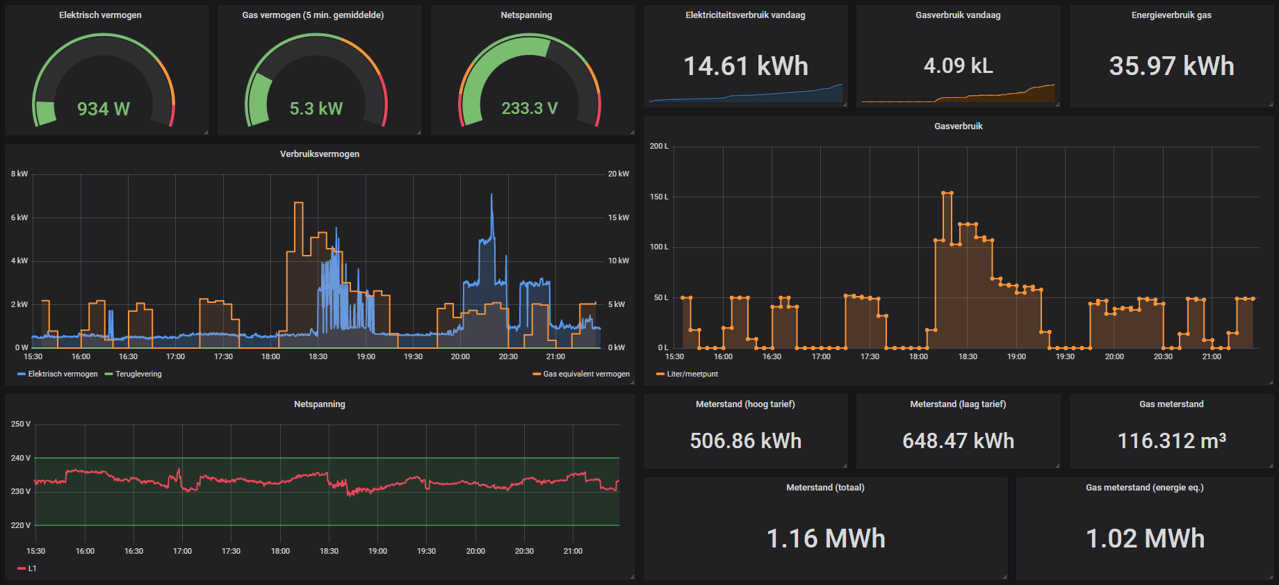
Telegraf, running on a Raspberry Pi in my LAN, is subscribed to the influx topic and forwards the received lines to InfluxDB on my VPS. There the data is stored, and can be accessed by Grafana which gives fancy graphs like this:
I had one minor but notable issue when switching from an Arduino Nano to a Wemos D1 mini for Wi-Fi reasons: the Wemos D1 mini wouldn’t run stably with just the power supply from the meter. It needs a capacitor to prevent the voltage from dipping too much when it momentarily draws a lot of current. I had some 470µF’s laying around, one between 5V and GND solved the problem.
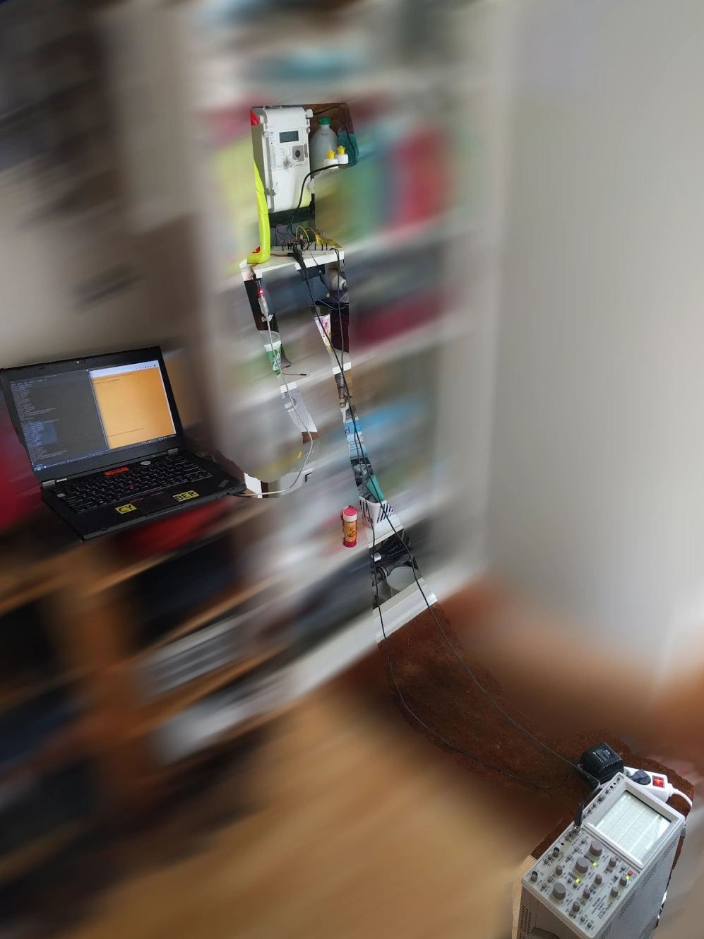
After I got the basics to work, for a while I didn’t have much time to solder a protoboard with the breadboarded circuit. Also, it kind of worked stably, it would only crash once every few days when somebody looked at it wrong. The semi-permanent setup looked like this for a few months:
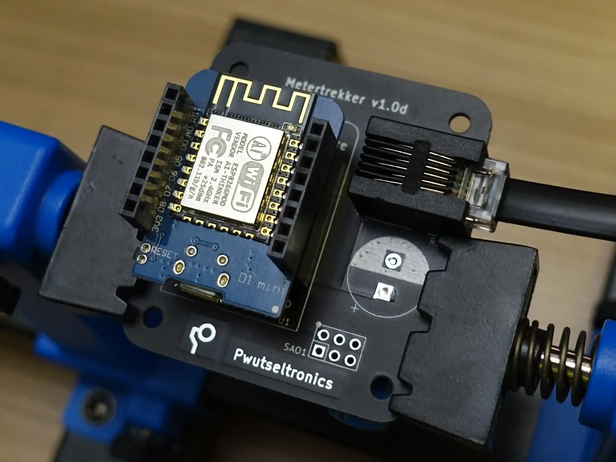
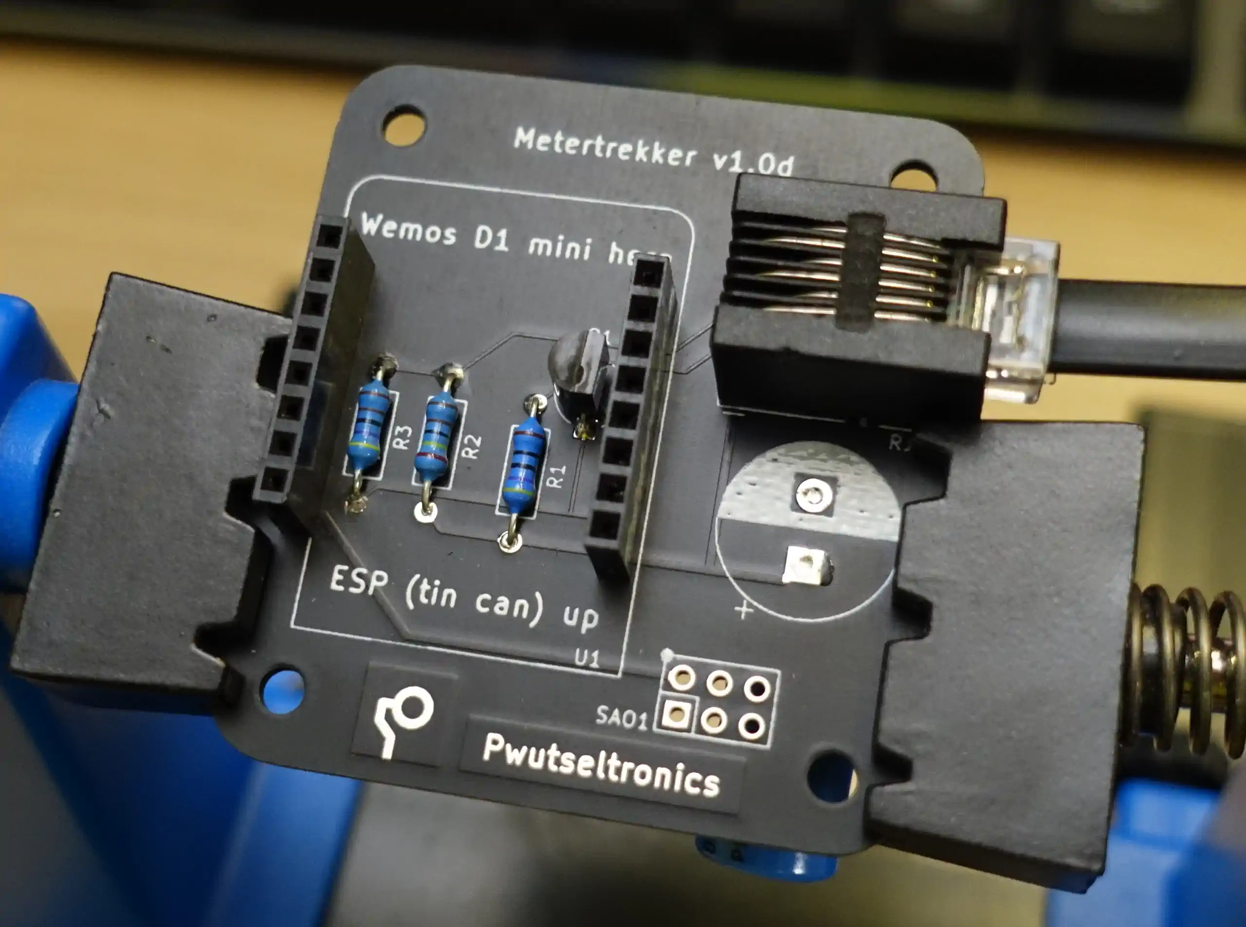
During eth0::autumn 2019, I decided to try to design a custom PCB to replace my crappy breadboard setup. The basic design was finished in one day and night (sleep is overrated when at hacker camps), but I kept tweaking it for weeks before finally ordering. I added an SAO (Shitty Add-On) connector in case anyone wants to add their shitty add-on to the Metertrekker, or even make one specifically for it to add functionality. It complies with the SAO v1.69bis spec by @BBenchoff. The result can be found below, I’m quite happy with it!
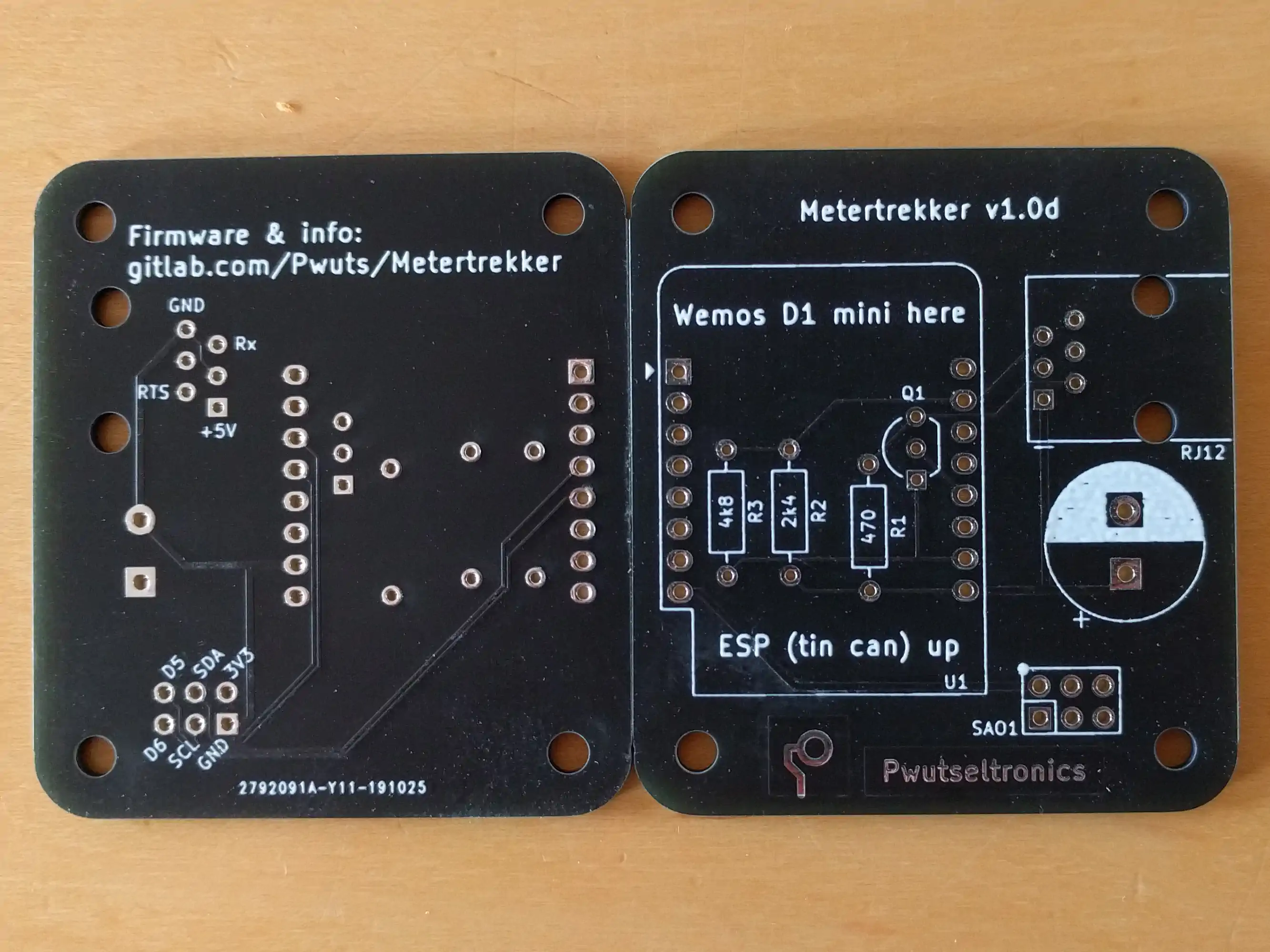
I have since ordered parts and assembled one (which I have had in use for ~3 months now, without crashes).


All in all, I set out to build something that would work for me specifically, and later found out it might be adapted to suit more people’s nerdy needs, so that’s what I’m working on from time to time.
At the time of writing this, my own setup has been running for months without crashing, multiple people seem to be interested to test my hardware and/or firmware, and someone has even made a derivative Wemos D1 mini shield! :)
TODO
Current points of attention are:
- source 220µF or 270µF capacitors; the 470µF caps trigger the overcurrent protection of the meter when connected. (currently temporarily fixed with a beautiful bodge)
- create enclosure
- test current hardware+firmware with more meters
- increase compatibility of firmware
- DSMR 2.2 support (-> make CRC verification optional)
- add support for other storage services, HTTP transfer
- explore feasibility of P02 communication for meters without P1
- create PnP version of firmware, connecting with smol cloud service (?)
Links
Firmware repo (GitHub)
PCB design repo (GitLab)
Product page
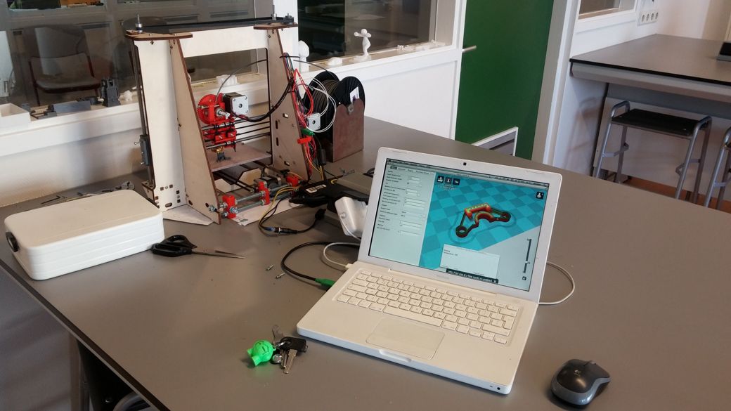 How I got into 3D printing
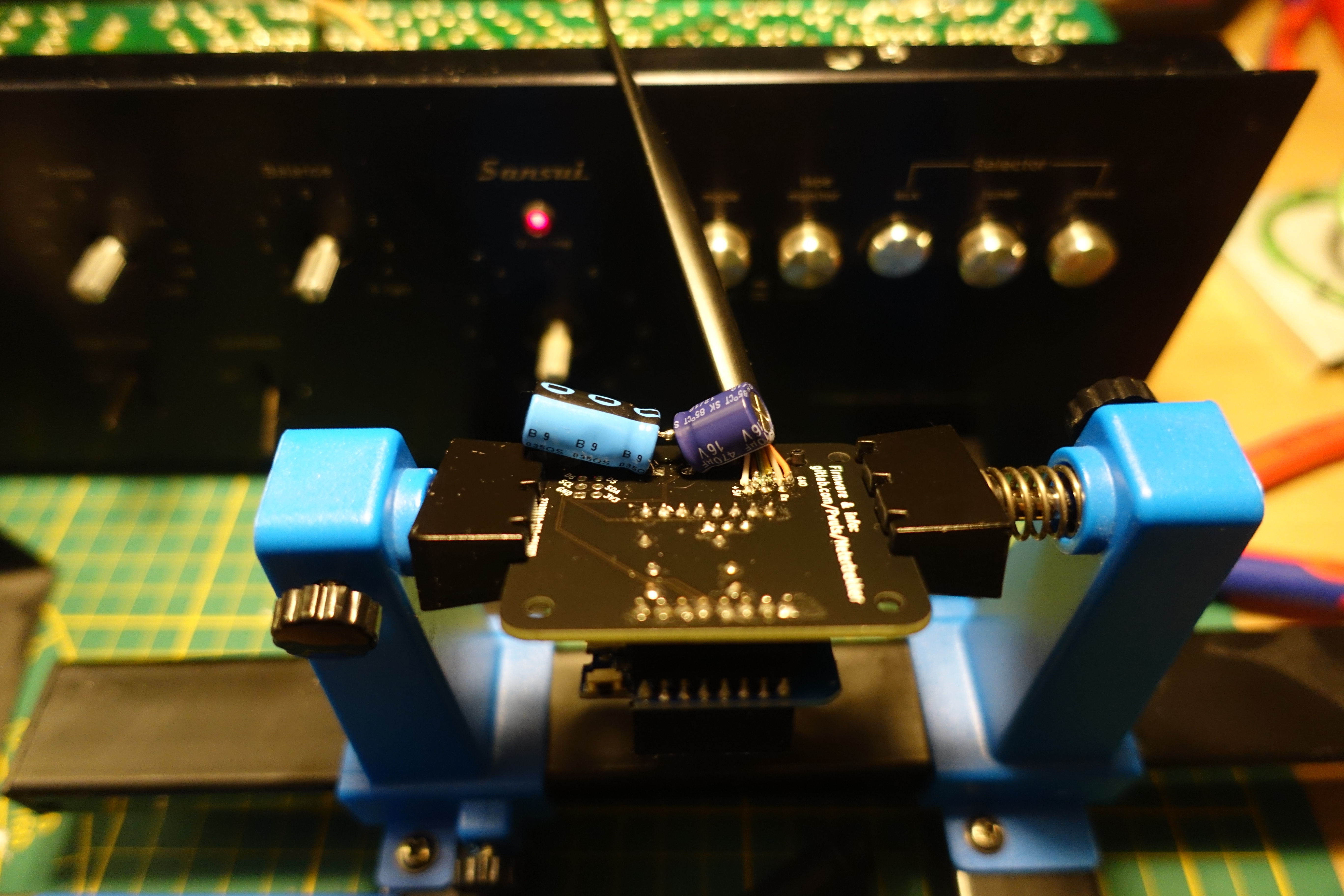